banner
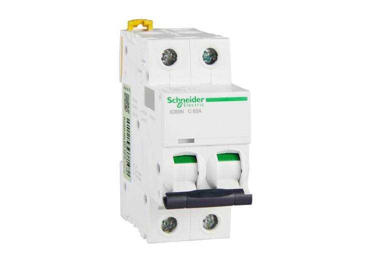
  • Schneider miniature circuit breaker
    Schneider miniature circuit breaker Sep 20, 2024
      Summary of Miniature Circuit Breakers Miniature circuit breakers include A9 (iC65, iDPN, etc.), M9 (C65, DPN, C120, NG125, etc.), E9, OSMC32N/OSMC65H, etc; Plastic case circuit breakers include: NSX, NSE, EZD, NSC, and large plastic case NS. Frame circuit breakers include MT, MTE, etc; Selection: 1. Determine the type of circuit breaker based on the rated current. 2. Select the series of circuit breakers based on their protection functions, that is, choose high-end or low-end products. 3. Select specific models (current, voltage, breaking capacity, accessories, special functions, etc.) based on conventional circuit breaker selection. Can Schneider C65 circuit breaker be used for electric motors? Answer: Schneider C65 miniature circuit breaker is mainly suitable for residential use, C65N/H is widely used in construction, industry and other fields, and C65L is mainly suitable for high breaking demand applications in industry, construction, energy and other fields. It can also control small electric motors.
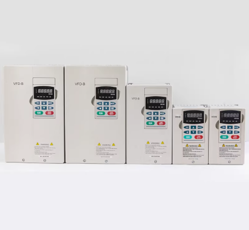
  • Delta inverter
    Delta inverter Sep 23, 2024
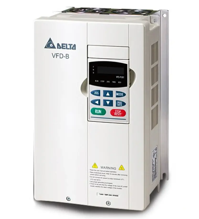
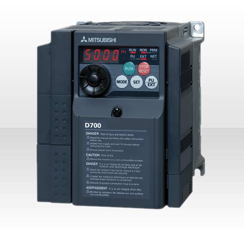
    The main functions of Delta inverter include: By changing the power supply frequency and controlling the motor speed, the goal of mechanical automation and energy conservation can be achieved. We provide various types of products, such as universal vector frequency converters, fan and pump specific frequency converters, universal economical frequency converters, high-performance magnetic beam vector control frequency converters, etc. By using specific terminal controls such as FWD forward control, REV reverse control, JOG inch control, etc., the frequency converter can achieve forward, reverse, and inch control. External abnormal input (EF) and external count input (TRG), as well as multifunctional input selection (MI1 to MI6), provide flexible operation and monitoring options. Digital frequency signal output (DFM) and multifunctional relay output contacts (RA, RB, RC) are used to output various monitoring signals, such as in operation, frequency arrival, overload indication, etc. In addition, Delta inverters also provide settings for motor stop modes, including deceleration brake stop and free running stop, to meet different application needs. These features make Delta inverters an important choice in the field of industrial automation, suitable for various application scenarios that require motor speed control and energy efficiency
  • The working principle of Delta inverter
    The working principle of Delta inverter Sep 26, 2024
    Brand Introduction   Delta Group is currently the world's leading manufacturer of switched power supply products and holds a world-class leadership position in multiple product areas, including providing comprehensive solutions for power management, video displays, industrial automation, network communication products, and products related to renewable energy. Energy saving principle 1. Variable frequency energy-saving The energy-saving of frequency converters is mainly manifested in the application of fans and water pumps. In order to ensure the reliability of production, various production machinery are designed with a certain amount of surplus when equipped with power drives. When the motor cannot operate at full load, in addition to meeting the power drive requirements, the excess torque increases the consumption of active power, resulting in the waste of electrical energy. The traditional speed regulation method for equipment such as fans and pumps is to adjust the air and water supply volume by adjusting the opening of the inlet or outlet baffles and valves. The input power is high, and a large amount of energy is consumed in the interception process of the baffles and valves. When using variable frequency speed regulation, if the flow rate requirement is reduced, the requirement can be met by reducing the speed of the pump or fan. According to fluid mechanics, P (power)=Q (flow rate) × H (pressure), the flow rate Q is proportional to the power of the rotational speed N, the pressure H is proportional to the square of the rotational speed N, and the power P is proportional to the cube of the rotational speed N. If the efficiency of the water pump is constant, when the required flow rate decreases, the rotational speed N can decrease proportionally, and at this time, the shaft output power P decreases in a cubic relationship. The power consumption of the water pump motor is approximately proportional to the rotational speed. When the required flow rate Q decreases, the output frequency of the frequency converter can be adjusted to proportionally reduce the motor speed n. At this point, the power P of the electric motor will significantly decrease according to a cubic relationship, saving 40% to 50% of energy compared to adjusting baffles and valves, thus achieving the goal of energy conservation. For example, a centrifugal pump motor with a power of 55 kW consumes 28.16 kW of electricity and saves 48.8% of electricity when the speed drops to 4/5 of the original speed. When the speed drops to 1/2 of the original speed, the power consumption is 6.875 kW, saving 87.5% of electricity. 2. Power factor compensation for energy saving Reactive power not only increases line loss and equipment heating, but more importantly, the decrease in power factor leads to a reduction in active power in the power grid. A large amount of reactive energy is consumed in the lines, resulting in low equipment efficiency and serious waste. After using a variable frequency speed regulation device, the effect of the internal filtering capacitor of the frequency converter reduces reactive power loss and increases the active power of the power grid. 3. Soft start energy-saving Hard starting of motors causes serious impact on the power grid, and also demands excessive capacity from the grid. The high current and vibration generated during starting can cause significant damage to baffles and valves, which is extremely detrimental to the service life of equipment and pipelines. After using the frequency conversion energy-saving device, the soft start function of the frequency converter will start the starting current from zero, and the maximum value will not exceed the rated current, reducing the impact on the power grid and the requirements for power supply capacity, and extending the service life of equipment and valves. Saved equipment maintenance costs. Usage environment 1. The ambient temperature ranges from -10 ℃ to+40 ℃. When removing the dust sticker on the upper end, it can be used for temperatures ranging from -10 ℃ to+50 ℃ 2. Prevent rainwater from dripping or humid environments 3. Avoid direct sunlight exposure 4. Prevent oil mist and salt erosion 5. Prevent corrosive liquids and gases 6. Prevent dust, cotton wool, and metal shavings from entering 7. Stay away from radioactive and flammable materials 8. Prevent electromagnetic interference (welding machine, power machine) 9. Install away from any heating equipment 10. Prevent vibration (punch press). If unavoidable, please install shock-absorbing pads to reduce vibration 11. When installing several frequency converters in the control panel, please pay attention to their placement for heat dissipation. Additionally, please install a cooling fan to keep the temperature around the frequency converters below 50 ℃. 12. Please advance the front of the frequency converter and keep the top facing upwards during installation to facilitate heat dissipation 13. The installation space must comply with the following regulations: If installed inside the disk or in the surrounding environment, the dust cover of the inverter can be removed to facilitate heat dissipation and ventilation of the inverter.
  • New Insulation Resistance Tester Fluke 1555
    New Insulation Resistance Tester Fluke 1555 Oct 14, 2024
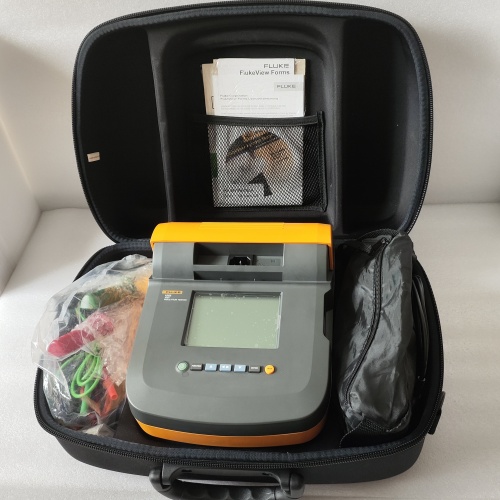
    Product Introduction The Fluke 1555 Insulation Resistance Tester is a specialized electrical testing instrument used to measure the insulation resistance of wiring, cables, motors, transformers, and other electrical equipment.  Fluke 1555   is a high-voltage insulation resistance tester developed and manufactured by Fluke Corporation. It is designed to test the insulation resistance of high-voltage power equipment, wires, and cables. Fluke 1555 has high precision and reliability, a wide measurement range, and is suitable for maintenance and troubleshooting of various industrial and power systems. It can provide reliable insulation test results and has a visual display screen and an easy-to-use interface. Fluke 1555 also provides various security features to ensure the safety of testing operations and comply with relevant security standards and regulations. It is one of the commonly used tools by professional electrical engineers and maintenance personnel to ensure the electrical safety and reliability of the system. Product Features 1. For the testing of windings with star connections and neutral point leads, the instrument can adopt a three-phase simultaneous measurement method to test the resistance of phases A0, B0, and C0, saving testing time. And first test the data of phase A0, and then test the three-phase simultaneously, which solves the problem of the inability to test the neutral point lead out resistance when testing the three-phase simultaneously, making the test data closer to the single-phase test value. 2. For the testing of Y-shaped and △ - shaped windings, the instrument can perform three-phase automatic testing and convert the three-phase unbalance rate. 3. The instrument has the functions of assisting magnetic testing and demagnetization, meeting various needs of on-site experiments. 4. The instrument has multiple protection functions such as back electromotive force protection, wire breakage protection, and power-off protection. 5. The instrument has a wide measurement range, up to 200 Ω, and high accuracy. 6. Clock and date display without power failure; The data storage methods are divided into local storage and USB storage, among which local storage can store 200 pieces of test data; The USB flash drive stores data in Word format, which can be directly edited and printed on a computer. 7. Thermal printer printing function, fast and silent. 8. Small size, light weight, convenient to carry and use. Technical Parameter single phase 20 A      0.500mΩ~1.000Ω 10A        1.000mΩ~2.000Ω 5  A      10.00mΩ~4.000Ω 1 A        100.0mΩ~20.00Ω 0.1A      1.000 Ω~200.0Ω three-phase 10A + 10A 1.000mΩ~0.800Ω 5 A + 5 A  10.00mΩ~1.600Ω 1 A + 1 A 100.0mΩ~8.000Ω  Accuracy ± (reading x 0.2%+2 words) Resolution 0.1u Ω Working power supply AC220V ± 10%, 50/60Hz Operating temperature -10 ℃~50 ℃ Relative humidity <90%, no condensation Instrument volume  410 × 290 × 220mm Instrument weight 9Kg (excluding testing line)
1 2

A total of2pages

Need Help? Chat with us

leave a message
For any request of information or technical support, fill in the form. All fields marked with an asterisk* are required.
Submit
Looking for Service?
Contact us #
+86 17620189681

Our hours

Mon 11/21 - Wed 11/23: 9 AM - 8 PM
Thu 11/24: closed - Happy Thanksgiving!
Fri 11/25: 8 AM - 10 PM
Sat 11/26 - Sun 11/27: 10 AM - 9 PM
(all hours are Eastern Time)      

home

products

whatsApp

Contact Us